ensqit
00355 674705037 Mon - Fri 07:30 - 18:00 Sat 7:30-12:00 Street Halit Bajraktari Shkoder - Albania
ensqit
00355 674705037 Mon - Fri 07:30 - 18:00 Sat 7:30-12:00 Street Halit Bajraktari Shkoder - Albania

ADAP-MOT

UNI EN 12845 NORMES STARTER FOR MOTOR PUMP OF FIRE-FIGHTING GROUPS (IN ACCORDANCE UNI 10779 NORMS)


Topographic Electronic Card

Description

Metal cabinet, IP55 of adequate size
Bipolar door-lock switch with adequate capacity
Programmable electronic board for control and management of the CMA motor pump as per the specifications given in the annex
Indication of alarms on the electronic board and display
Man - 0 - key selector selector
N°2 12V battery charger with microcontroller control complete with 230V-14V transformer
Battery check on the electronic board
Protection fuses
Digital tachometer
N ° 2 Power contactors
Emergency button
Differential magnetothermal for engine oil heater
Alarms type "A" and type "B"
Wiring and terminal board
Electrical scheme and certification
Power supply 230V (F + N) 50 - 60Hz
The graphics can be customized on your request.
The software of the framework can be in both Italian-English-French language and must be specified when ordering.


Code Power at 400V Dimensions (mm)
MOT11000 HP-5,5-150    KW-4-110 600x400x200


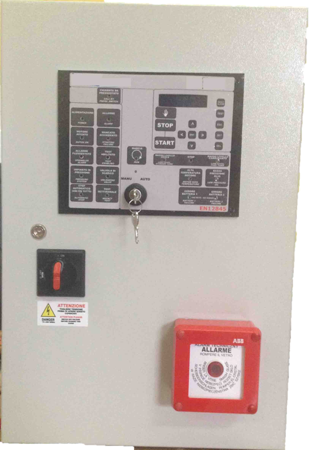
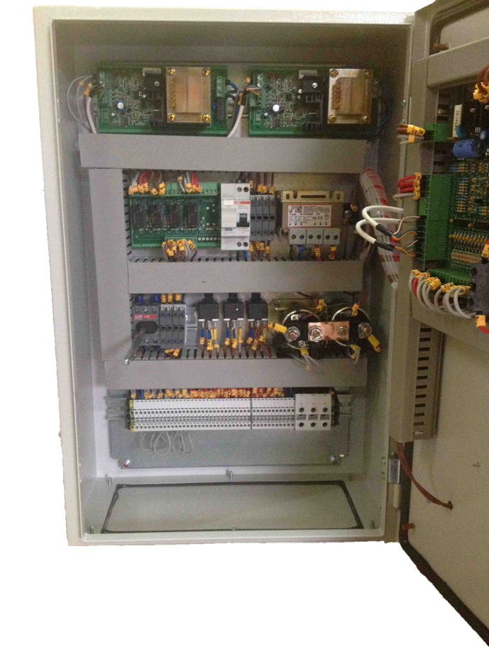
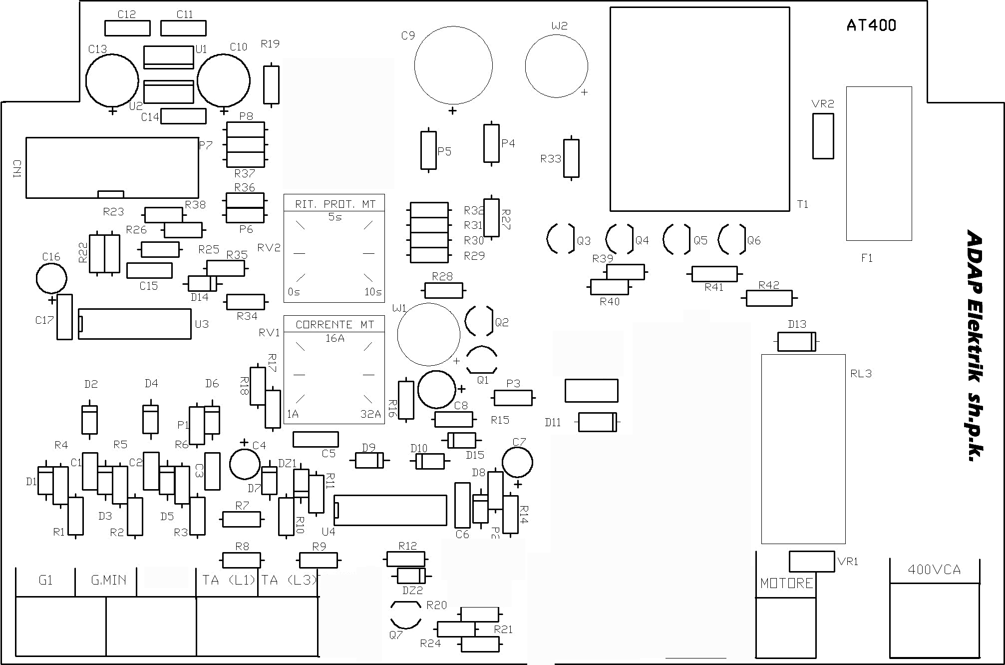
Instruction manual Electronic board electrical panel ADAP-MOT

Instruction manual electronic board ADAP-MOT


Technical Date

  • Protection fuses for relay and electronics components;
  • AUTO / OFF / MAN operating modality selector switch with key extractable at the position AUTO only;
  • Alpha-numeric, high visibility illuminated blue LCD monitor;
  • Automatic and manual LED test;
  • Simplified navigation keyboard;
  • 60 Alpha-numeric and graphics characters available;
  • Messages at display in three languages (Italian, English, French);
  • Programmable by keyboard internal clock and calendar with display of YEAR / MONTH / DAY of the WEEK / DAY of the MONTH / HOURS / MINUTS / SECONDS;
  • Weekly test directly programmable by keyboard;
  • Weekly test exclusion;
  • Restoring of normal operating modality at the end of weekly test;
  • Restoring of normal operating modality in case of fire during the weekly test;
  • Storage settings on EEprom ram memory;
  • Control of input signals with protection against electrics discharges and electrostatics;
  • No-bouncing inputs controlled by software;
  • Very low voltage (5 V) and very low current (< 0,5 mA) inputs;
  • RS-485 serial port for alarms sending and resetting to up to 500 metres with dedicated control panel MC-PAR;
  • I2Cbus internal serial port for communication with other electronic cards;
  • In-Circuit software update;
  • Possibility of stopping the pump at the restoring of pressure;
  • Programmable number of start attempts;
  • Programmable duration of start relay excitation;
  • Programmable duration of pause among start attempts;
  • State indication by means of high luminosity LED for:
  • call from pressure switches (START BY CALL – PRESS. SWITCH);
  • call from pressure transducer (START BY CALL – PRESS. TRANSD.), F.P.A. Norms only;
  • Power in (POWER);
  • General alarm (ALARM);
  • MOTOR ON;
  • STARTING FAILURE;
  • SPRINKLER ALARM;
  • TEST ENABLING;
  • PRESSURE SYSTEM;
  • UNLOADING VALVE;
  • AUTOMATIC STOP (UNI EN 10779 Norms only);
  • WEEKLY TEST;
  • RUN;
  • LOW LEVEL STORAGE TANK;
  • LOW LEVEL FUEL TANK;
  • LOW PRESSURE TOWN MAINS;
  • MOTOR HIGH TEMPERATURE;
  • LOW PRESSURE OIL;
  • LOW TEMPERATURE ROOM;
  • BATTERY 1 FAILURE;
  • BATTERY 2 FAILURE;
  • Main power failure (BATTERY 1 FAILURE and BATTERY 2 FAILURE);
  • STOP;
    • Messages at display for:
  • Date, time (hours, minutes and seconds), norms and key position;
  • State of charge of both batteries;
  • Key position;
  • Motor stopped;
  • Call from pressure switches;
  • Call from pressure transducer;
  • Call for priming;
  • Start for priming;
  • Number of starting attempts;
  • Length of starting attempts;
  • Pause between two starting attempts;
  • Motor running;
  • Starting failure;
  • Start with battery 1;
  • Start with battery 2;
  • Start with batteries 1 and 2;
  • Waiting for motor stop;
  • Weekly test in progress;
  • Fuel level (0 ÷ 100%);
  • Low Level fuel;
  • Oil pressure (1,0 ÷ 10,0 bar);
  • Motor temperature (10°C ÷ 130°C);
  • Running hours meter;
  • Motor RpM.
    • Reset of alarm display;
    • Acknowledgement of acoustic alarms;
    • START/STOP by means remote control (not included);

Analogue Inputs:

  • Fuel level (0 ÷ 100%);
  • Motor oil pressure (1,0 ÷ 10,0 bar);
  • Motor temperature (10°C ÷ 130°C);
  • Battery 1 level;
  • Battery 2 level.

Digital inputs:

  • 2 NC (Normally Closed) pressure switches for fire detection;
  • Float switch for priming tank of pump;
  • Flow switch for sprinkler of pump room;
  • Pump room temperature;
  • Low level of storage tank (read low pressure town mains in case of supply by town mains);
  • Storage tank empty;
  • System in pressure;
  • External start and stop buttons;
  • Low pressure oil pump;
  • High temperature water pump or oil pump;
  • Low level fuel tank;
  • Pick-up for round meter.

Outputs:

Free contacts for:

  1. Type A Alarm;
  2. Type B Alarm;